Yesterday marked the second anniversary of this blog.
What a difference two years makes in a life.
How a machine can contribute so much remains a little bit of a mystery to me.
Of course it's not the machine. It's really just me, changing the way I relate to the world around me. The Vespa is just a new mode, a filter, that alters both reality, and perception.
This blog is also an important part of the change in me.
At first it was just me, sharing my experience to help others like me who were interested, but who knew too little about the reality of riding.
More than a filter, the blog has become a two-way lens. Letting others see me, has let me see others too. I know that I have friends and acquaintances in far-flung places. These are real-life relationships that, like all friendships, add richness to the life I live.
I'll be in Vancouver in May, staying at one of the downtown Fairmont hotels. The schedule is a little tight. I fly in the morning of Thursday, May 24, and leave on Sunday evening, the 27th. I'll be spending as much time as possible with my son but also want to meet as many of you wet coasters as possible, you know who you are. Send me an e-mail and let's see how many of us can gather. Bob has made very gracious arrangements for a 200cc ride for me. A group ride ending somewhere we could sit down to grab something to eat would be really nice. Maybe I'll be able to convince my son Andrew to ride pillion.
I'll be sure to bring all my gear, so it could be rain or shine.
I knew that I had to pull all the stops for the ride home.
Minus 1 Celsius, warmer than this morning's commute by three degrees, but the wind that was strong this morning, had picked up considerably.
I zipped the liner into my armored pants, threw my Teknic rain jacket on over my armored jacket, and put my thin wool glove liners on under my winter gauntlets.
So many layers is not comfortable. I felt cumbersome.
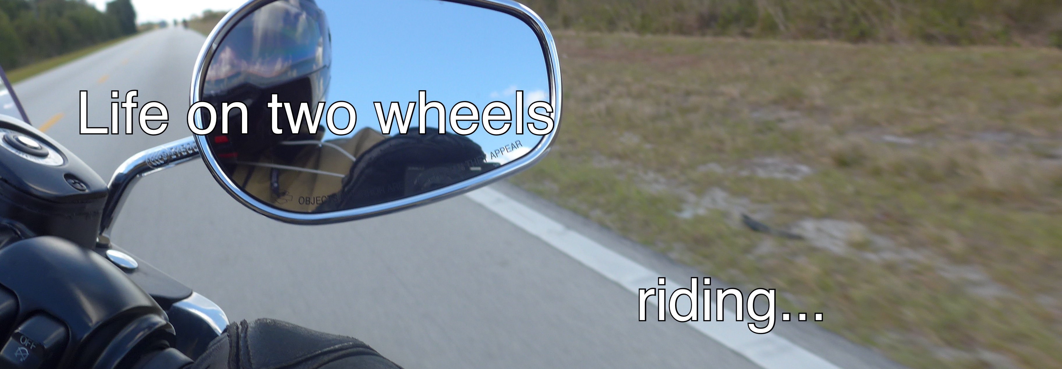
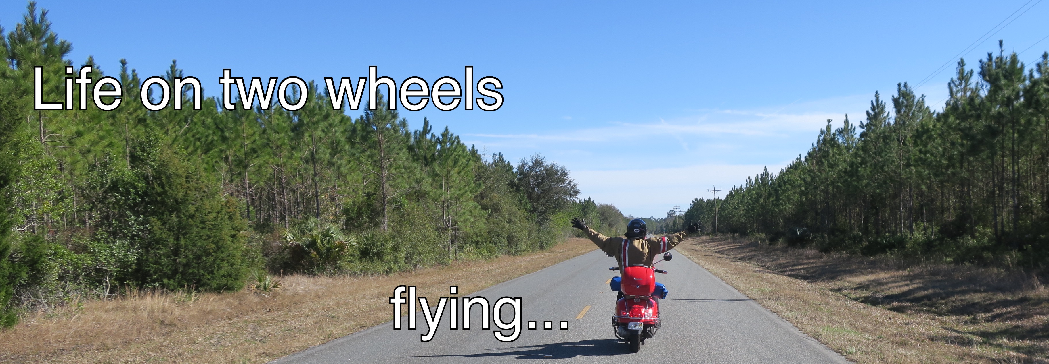
When I ride, I feel light and weightless, I swoop over the landscape like a bird in flight. With all that gear on I feel more like an astronaut than a pilot.
As soon as I rolled out of the garage I cranked up the juice to the grips to the max.
I decided on the fastest route. Wide open throttle on the expressway all the way home.
The wind gusts were ferocious. Stronger than I've ever experienced. Actually shoving the bike around in the lane. I focused on riding, tense, alert, constantly ready to counteract the gusts.
A couple of eighteen wheelers added their turbulent after-drafts to the challenge. For the latter half of the ride I followed an off-duty fire truck, peeling off the formation at my exit and decelerating down the ramp as the firemen thundered along the expressway headed further west.
So much speed, so much wind-chill. And yet the one thing I didn't experience was cold. Not a bit. My hands? Usually the weak spot. Tonight? Toasty!
My upper body? With the rain jacket blocking all the airflow, also, well, neutral says it best. Not hot, not cool, just normal.
My legs and lower body? Same as the top half.
Same story was playing out in my Icon Patrol boots.
As many have remarked before me, it's all about the gear.
Over all, this kind of experience is not why I ride. Too much gear to feel like I'm flying.
Tomorrow snow's in the forecast, so I'm trading the Vespa for the Civic.
Minus 4 Celsius or 25 Fahrenheit coupled with stiff winds out of the north. This is the March I remember. Freaking cold.
The Hot Grips™ were running on the maximum setting this morning. No half-measures for a day like this.
The visor had to be snapped shut to keep the sharp knife of cold air from freezing my nose. My Corazzo underhoody did its job of sealing the gap between my Corazzo 5.0 jacket and Nolan N-102 full-face helmet.
The heated grips made all the difference.
Nevertheless, it was so cold, particularly with the wind factored in, that more countermeasures were dancing in my head. Such as:
I should have put the liners in my armored pants (Dohhh!).
I wonder how nice it would be with heated grips and muffs?
A true all-weather jacket with a removable liner would be a really nice touch.
You can tell it's unseasonably hot when students decide that a $500 tuition fee hike is so fundamentally offensive to their civil rights that they paralyze a metropolis for hours on end.
Sheesh, you'd think that the G8 was in town for a kaffeeklatsch.
You know it could get tough, when the horses think to wear their soccer shin pads and paintball visors to the party!
The men in blue also brought dogs wearing their doggie SWAT suits. No sense in letting the horses have all the fun.
This morning, the heaviest fog yet. I had to stop three times, remove my helmet, switch my glasses (Ray Bans to regular, back to Ray Bans), switch gloves (summer gloves to gauntlets, back to summer, back to gauntlets). Started warm, got chilly, back to warm; started out sunny and grey, became pea soup fog, then sunny, back to pea soup, back to sunny.
Things stabilized as soon as my route left the lake shore.
The fog is coming off the lake. Something to do with warm air, very cold lake water, residual ice banks here and there... at least that's my uneducated non-meteorologist's guess.
It slowed me down, but blew me away. I love fog. It proves to be much, much trickier on two wheels.
If this keeps up, I may figure out a strategy. I'm beginning to think that the right strategy is to button down. Shut the visor, and then squeegee when the fog pearls up on the visor. That means sticking with the Icon Patrol gauntlets that have the squeegee built in on the left index finger.
Then again, this is season three of life-on-two-wheels, and these are my first encounters with fog.
There may be no time left to learn.
Any thoughts?
PS: that's Stewart Hall in the background, and no, I don't live there, nor do I own it.
I had to pause on the way home yesterday on my first commute of 2012.
The photo says it all: an August blazing fireball sunset in mid-March. Who would have thought that warm weather like we're enjoying was even remotely possible on the first Monday after St. Patrick's Day?
On the way home tonight, people were dining on the sidewalk terrace at Il Fornetto in Lachine. And there was a crowd scene at the Dairy Queen.
Tomorrow's forecast is even hotter! HOTTER!?!? Yes, hotter.
The Creator must be mocking me for installing heated grips on a Vespa LX.
The 2012 Vespa scooter commuting season officially kicked off this morning.
The heated grips I installed weren't needed due to the unseasonably balmy weather we've enjoyed since Sunday when the temperature hit 21.5C.
This morning it was cool. I switched the grips on to a low-ish setting, just because I could. So there, global warming, take that!
In two years of commuting on my scooter this was my first experience with fog. The fog was rolling in from Lake St-Louis, and was at times quite heavy. The main concern with the fog, aside from the obvious challenge of seeing and being seen, was that my visor fogged. It was so troublesome that I had no other option than to ride with the visor up.
Given the warm temperature, it wasn't a problem.
This morning I am also sporting my new Icon Patrol boots.
This picture was taken yesterday when I went for a brief joyride. When I commute I wear full gear including lined Tourmaster Caliber pants. Yesterday I ventured out in jeans.
The season begins with 10,778 miles on the clock. I mention it just so I can record it here in case I'm wondering later on how many miles I will have logged this season.
It certainly feels good to be back on two wheels. I'm taking it slowly. Nice relaxed commuting along the scenic route. At least until I've got my sea legs back.
Make yourself some tea or coffee, and settle in, because it's the most ambitious of my modifications to date, so it's going to take a while to read and understand it.
This project is a challenge on a number of levels, including delays resulting from a rookie mistake that destroyed the first Heat Troller®. If you want to skip right ahead to see where I messed up, scroll down to paragraph 110 below, or click here.
Since it's an electrical project, and since heated grips demand a lot from the electrical system on a Vespa LX150, there was a learning curve before I could even commit to the project because I needed to make sure that the bike could handle the modification. I came to the conclusion that, while the electrical budget will be tight, it should work just fine. To follow me down that preliminary path, click on the "The gear posts" link above, scroll down the list to the heated grips project, and read the posts that discuss the electrical system and the electrical requirements for heated grips.
The other challenging aspect of this project for me, was having to take the stock grips off. As you'll see, it's a little bit of a challenge, but there are some techniques that work really well, and in the end, I managed it quite well.
So let's get started. You'll see that I've numbered the paragraphs to make referring to the instructions easier, if need be.
Tools
Phillips screwdriver (preferably with a magnetic tip)
Long slim electrician's screwdriver
Electric heat gun
Electric drill
3/8" drill bit
1/8" drill bit
Medium grit sandpaper
Bamboo skewer or small dowel
Paper plate
Adjustable crescent wrench.
Scalpel
Pliers
Supplies
High temperature epoxy adhesive Hot Grips™ heated grips Warm & Safe Heat-Troller® electronic temperature control unit
12-14 gauge solderless wiretaps
Small plastic wire ties WD40, Motomaster aerosol white grease, or other automotive aerosol lubricant
Rubbing alcohol
Dielectric compound or grease
1. First off, it's January, and though the garage is heated, it's still chilly in there. My solution and first step was to hang my heat gun from the ceiling and leave it running on the high setting. Not the most efficient way to raise the temperature, but effective none the less.
2. Meet the patient:
3. The first step is to open up the bike to get at the components.
4. Using an adjustable crescent wrench, loosen the compression nuts on the windshield supports. I took the precaution when I installed the windshield to grease the mounting hardware and mounts. Once the compression nuts were loose, I simply applied pressure to the mounts, pushing them hard into the bike, towards the headset. This counter-intuitive step actually forces the compression sleeve out of the split shaft and releases the pressure. With that done, the windshield mounts slid right out.
5. Next step: remove the horn cover panel. This is almost always the first step in any Vespa project. and the first thing to do is to remove the Piaggio badge. Protect the paint from your flat blade screwdriver and gently pry the badge away from the body, using the slot in the side of the badge.
6. Removing the badge reveals the screw that holds the horn cover in place. From now on, all you need is a Phillips (star-shaped) screwdriver.
7. At this point, it's time for some advice. This is going to be a long project. It could be weeks before I button the bike up again. Even though I've taken my Vespa apart many times now, I don't want to take any chances. To make sure that there are no surprises when I'm wrapping the project up, I like to place the parts I remove in ziplock sandwich baggies along with a slip of paper with the step number, and a description of the part. There may be other ways of doing this, but this works for me.
8. With the horn cover off, two more screws are revealed. Those screws are two of the five screws that hold the back of the leg shield on (that's the large plastic piece that has the glove box in it).
9. Remove those screws, and then remove the mirrors. Raise the rubber boot that covers the nut at the base of the mirror stem. Use an adjustable crescent wrench to loosen the nut, then grip the mirror stem and firmly rotate the stem counter-clockwise to remove the mirrors.
10. With the two front leg shield screws out, and mirrors off, find the screw in the centre of the headset, and just below the headlight, and remove that screw. Be very careful removing that screw, and it's best to use a magnetic screwdriver. If that screw falls, the odds are that it will fall inside the bike and rattle down along the inside of the legshield and down under the floorboard. For this project I don't need to remove the floorboard since I already have all the necessary wiring from the battery done as a result of previous projects. I took great care not to drop that screw.
11. Here's a shot of me, taking care in removing the front headset screw.
12. The next step I took was to remove the two other screws that hold the front portion of the headset on (that's the portion with the headlight and turn indicators. Those screws are located on the back of the headset just below the controls. There is one screw on the right (pictured) and one screw similarly located on the right side.
13. With the three headset screws removed, carefully, very carefully, wiggle the front of the headset loose. There are two retaining clips, that if you look carefully, you'll find right next to the handgrips. You need to release those clips.
14. Many, many, many Vespa owners end up snapping one of those clips off. Kudos to you if you manage the removal without damaging at least one of those clips. I snapped one off, on my first project. As far as I can see, having one too few of those clips, there is no consequence that I can measure.
15. Here's a picture showing what the clip looks like:
16. With the clips released, a little gentle wiggling and prying and the headset cover will release.
17. It won't come completely free because it's tethered to the bike by the headlight and turn indicator wires. Those have quick release connectors, Unplug the headlight, release the other connectors, and the headset cover will come right off. Be careful not to drop it.
18. We're getting close to where we need to be. Next up, tackle the three last screws: those inside the glove box that hold the leg shield cover on.
19. The screws are easy to find once you open the glove box. They are in a triangle configuration. Two on the bottom, one on each side...
, and one centered at the top.
20. With the last two screws out, it's time for more wiggling and coaxing. The leg shield needs to move down and back to come free. Take your time removing it and pay attention. The reverse coaxing and wiggling will be required to re-install it at the other end of the project.
21. With the legshield free, it's much easier to show off two of my earlier modifications: a 12 volt accessory outlet in the glove box...
22. ... and the GT style bag hook. Both these modifications make the Vespa LX 150 a much more versatile ride: the 12 volt outlet charges cell phones, and powers a GPS unit, and the bag hook adds a second load carrying option, and is just plain handy.
23. Finally, the Vespa reveals all of its secrets.
24. All the parts removed, they move into the house to be stored in the basement until the project is complete and they can be re-installed.
25. It's now time to tackle the bits I had no experience with, and that, frankly, made me a little nervous: removing the Vespa's hand grips.
26. Since I was most concerned about the throttle side, that's where I started.
27. My hunch was that if I used the heat gun on the low setting and gently heated the grip, the rubber would loosen up, and I'd be able to work the grip away from the rear headset cover without damaging the grip, the headset cover, or the throttle tube and mechanism.
28. I set to work with the heat gun, being very careful not to apply heat to the plastic body parts. Those parts are themoplastic, and heat from the gun could easily ruin the headset cover.
29. Once I got the grip as hot as I could hold with my bare hand, I began by wedging my fingers between the headset and the large flange of the grip. The hot rubber was pliable enough that I was able to roll the flange back to reveal a bit of the throttle tube.
30. To my amazement and great satisfaction, the grip began to back off the throttle tube!!!
31. The grip had cooled, and progress stopped. A little more judicious use of the heat gun, some more wiggling and twisting, and presto!!
32. The throttle tube that hadn't seen the light of day since the factory in Pontadera, Italy:
33. Here's a look at the end of the tube. There's metal in there, somewhere. Solid metal. No hollow bars on a Vespa.
34. Hmmm... can you tell I'm dreaming of nice shiny bar-ends? SSSSSNAPPP OUT OF IT DIMWIT!!! Only one project at a time!
35. On to the left grip.
36. Different grip, different challenge. On the left side, things are less dicey, since there's no throttle tube to bugger up.
37. No doubt for that reason, heating the grip accomplished nothing much. All nice, hot and bothered, but not budging at all. No worries, I had done my homework.
38. Out with the long slender electrician's screwdriver, and out with the aerosol grease.
39. Truth be told, the recommendation is to use WD40. But I don't have any, and I'm guessing that white grease will do the trick and spare me a trip to the hardware store.
40. Fortunately there is enough free space on the left side of the headset to work the electrician's screwdriver between the grip and the handlebar. That allowed me to open enough of a gap to spray some grease in.
41. Different tactic, but same result. The white grease worked wonders. With very little additional effort, there sat my wonderful Vespa, gripless.
42. I used some rubbing alcohol to give the throttle tube and the left bar a good cleaning, and remove any trace of the white grease. That concluded the demolition phase of the project.
43. I headed back into the house to ponder the construction phase. First I fetched the Hot Grips™ to test how they fit and to pay attention to the position of the grip on the throttle side, to make sure that the rotation of the throttle relative to the heated grip feed wire wouldn't bind in a way that the wire would interfere with the controls, or vice-versa. I concluded that the wire from the grip should be roughly in the five o`clock position, seen facing the end of the grip.
44. They slid on easily with no resistance. So easily that once on the bike, they actually wiggled a little. Way too loose. That's what the epoxy glue is for. Oh joy.
45. Now for a brief digression on epoxy glue. Hot Grips™ recommends a specific brand of high temperature epoxy glue. I thought I had ordered some with the grips, but apparently not.
46. A visit to Home Depot's adhesive department revealed a Lepage brand marine epoxy rated as both waterproof, and temperature resistant to 305F. A careful read of the Hot Grips™ recommendations on epoxy glue, and I was satisfied that the Lepage product would do as well as the Devcon product recommended by Hot Grips™.
47. In the comfort of my family room, I carefully read and re-read the Hot Grips™ instructions, and the instructions for the Heat-Troller®.
48. My plan is to take the power for the Hot Grips™ from the leads to my 12 volt outlet. The outlet gets its power and ground directly from the battery on 12 gauge automotive wire. The line has a 25 amp fuse at the battery to support the needs of the Stebel Nautilus air horn. The line that feeds the outlet and the air horn is switched by a relay that gets its switching current from the left running light. There is also a 10 amp fuse for the outlet. That fuse will be fine to protect the heated grips as well. That way of wiring the grips means that the power to the grips (like the power to the outlet and the air horn) will only be on when the ignition is on. That's a good thing because it means that it won't be possible to leave the grips running when I turn the bike off and remove the key. That's the configuration that Hot Grips™ recommends.
49. Because a diagram may prove very helpful to others attempting this modification, I took the time to make a circuit diagram. If you need to see the diagram more clearly, click on it and it will open in a larger version in a new window.
50. I took the Heat-Troller® and its wiring harness and control box out to the garage to get an idea of how I would install it. The switch will fit nice and snugly into the rear headset, just above the brake. There's enough clearance there. Here's a shot showing the switch and it's eventual location, more or less.
51. The control box I plan to set in the leg shield on the right side, holding it in place with the supplied hook-and-loop fastener supplied with the unit. Here's a general idea of where it will go:
52. It was getting to be late afternoon and the time allotted to the project was drawing to a close for the week. I didn't want to call it quits without getting the new grips installed on the bars.
53. I decided to tackle the left grip first, just because it's installed on the metal bar, not on the throttle tube, so I perceived the risk of screw ups with the epoxy glue to be less.
54. The first step is to mix a batch of epoxy glue. I used a paper plate and a four inch length of bamboo skewer.
55. The consistency of the mixed epoxy was just right and buttering up the grip was a cinch. The inside diameter of the grip in relation to the handlebar was perfect to allow the grip to slide on to the bar, with just enough resistance resulting from the epoxy, but without the grip "plowing" a bow wave of glue and causing a mess. Once positioned, I could tell it was an excellent fit. It was a lot easier than I anticipated.
56. Here's a shot of the left grip once installed with the epoxy.
57. With my self-confidence on the rise, it was time to tackle the throttle side.
58. The first step suggested by the manufacturer is to use some sandpaper to roughen the surface of the plastic throttle tube.
59. Piece of cake, and maybe a thirty second job.
60. I made up a second batch of epoxy and buttered up the throttle tube. I took care to leave the end of the throttle tube free of epoxy to that even if installing the grip pushed some expoxy forward, it wouldn't compromise the throttle mechanism.
61. As you can see in the following picture, the grip is nearly all the way on, and there is no epoxy protruding.
62. I slid the grip the rest of the way on and made sure that the wire from the grip was in the five o`clock position.
63. Satisfied with my progress, the last little bit I fussed with was finding a path for the wires from the Heat-Troller® control box in the leg shield up to the headset. I found room in the retaining clip for the wire loom headed to the headset and clipped the main control lead wire in there.
64. So that's how the first day of the project ends.
65. When I came home from work on Monday evening, I tested the feel of the grips and they were appropriately rock solid and the throttle operation was as smooth as ever.
66. The Hot Grips™ have a slightly larger diameter than the stock grips and I like the way they feel.
67. Next weekend: electrical connections, installation of the dash-mounted control switch and status LED, and testing.
~~~~~~~~~~~~~~~~~~~~~~~~~~~~~~~~~
68. It has been two weeks since I physically installed the Hot Grips™ heated grips on the Vespa's handlebars.
69. The interruption in the project has absolutely nothing to do with this job, so if you are doing a similar installation please don't feel the need to allow for similar gap. It's true that the epoxy needed to set, but overnight will do just fine.
70. Anxious to get a feel for the results, so to speak, it's high time to plunge in to the electrical side of the project.
71. I'm using solder-less wiretaps to hook the Heat Troller up to the Vespa's electrical system. Solder-less wiretaps are well suited to motor vehicle work because they are unlikely to be affected by vibration (unlike Marr wire nuts), they are less invasive (no cutting or stripping required) and I'm lazy (no awkward soldering in the cramped quarters of the Vespa's leg shield, in the cold garage.
72. As mentioned a few weeks ago, I am taking the power and ground for the Heat Troller® from the leads that go to the 12 volt power outlet I installed on the Vespa when I first got the bike. That outlet is installed on 12 gauge power and ground lines that run directly from the Vespa's battery. The outlet is protected by a 10 amp fuse and is controlled by a relay. The relay coil is wired to the positive lead that goes to the left front running light. This setup means that none of my modifications rely on tbe Vespa's nervous system for power. Everything runs directly from the battery.
73. Throwing the relay into the design ensures that my added toys only operate when the ignition is on. That means that when I take the key out of the ignition nothing (especially not the heated grips) will be running the battery into the ground (pardon the pun) while the bike waits for its next outing.
74. Just a reminder that there is a wiring diagram above that shows the electrical circuit. If you want to see that in a separate screen to make it easier to see or print, click here.
75. Nothing could be simpler than wiring up the Hot Grips. Just follow the manufacturer's instructions.
76. Use solder-less wire tap connectors and a pair of pliers to compress the connectors to attach the red wire coming from the Heat Troller® to the positive (in my case red) power line. Attach the black wire coming from the Heat Troller® to the ground wire (or any grounding point, really). I use the ground line from the battery because I know it's a really good ground.
77. Here is a photo of the power connection.
78. The automotive spade connectors attach to the leg shield 12 volt power outlet. You will see that my ground line is yellow. I like to break with convention. At the time I upgraded the ground line last winter, the only 12 gauge automotive wire I had on hand, other than red, was yellow.
79. With those connections done, the next step is to connect the grips.
80. The grips attach to the blue and white wires that come from the Heat Troller®. The grips don't care about polarity. That means that either of the black wires from the grip can be attached to either the white, or the blue, Heat Troller® wires. The Hot Grips™ heated grips are wired in parallel, NOT IN SERIES.
81. That's fancy electricians' jibber-jabber that means each grip is wired directly to the Heat Troller®.
82. If they were supposed to be wired in series (WHICH THEY ARE NOT), one wire from one grip would be wired to the blue or white wire, and the other black wire would be wired to the other heated grip wire... If that's what you are busy doing, PLEASE STOP NOW!
83. Now that we're (hopefully) clear on what wiring the grips in parallel means, let's do it.
84. Starting with the left grip (seen from the riding position, not the throttle-side grip), route the wire from the grip towards the other cluster of wires that make their way down from the headset into the leg shield.
85. Use a solder-less connector to connect one of the black wires to the blue wire from the Heat Troller®, and the other black wire to the white wire.
86. Here's a photo of the connections between the Heat Troller® and heated grip wires.
87. Now repeat those steps for the throttle-side heated grip, FOR WHICH THERE IS AN ADDED STEP!
88. Because the throttle-side grip must rotate, make sure to allow enough wire between the grip and where the wire will enter the headset, near the brake lever, to form a curve of wire with a radius of at least two to three inches. This ensures that repeated strain on the wire resulting from twisting the throttle (there will be a lot of twisting of the throttle, he thinks, with a big grin) will be minimized.
89. Here is a picture showing how that looks on my Vespa.
90. With all those connections made, it's time for the moment of truth.
91. Switch the ignition on. Now give the Heat Troller® dash control knob a clockwise twist to the low "on" position.
92. The LED should be flashing. The LED comes on when power is being fed to the grips.
93. Turn the control clockwise to the maximum heat position.
94. This photo shows the LED on the Heat Troller® dash control glowing merrily.
95. Feel the heat. Ahhhhhhhhhhhhh!!! Can't wait for the spring scoot commute.
96. If you're like me you'll want to just stand there in your garage feeling the joy. Then your thoughts will drift to the battery. How is it performing under this new load?
97. First I hooked up my trusty Motomaster multi-meter to the 12 volt power outlet leads. I set the heated grips to medium.
98. Here's a video of what that result looks like.
99. Then I hooked the multi-meter up to the leads from the battery. Here's what that test looks like.
100. I have no idea what this reveals, other than the Heat Troller is doing its job of managing the load on the battery. I know a highly trained electrician and I'm going to have him take a look and interpret what the meter is saying about power consumption. I'll post his observations when I get them.
101. Next step: Installing the control in the dashboard.
~~~~~~~~~~~~~~~~~~~~~~~~~~~~~~~~~
102. The first step in installing the dash-mounted controller is finding a good place for it.
103. I chose the left side of the dash because, should I want to adjust the grips during a ride, the only free hand will be the left one. I chose to install the control on the rear half of the headset assembly because a) it makes sense to keep the controls clustered there, b) there's room on the inside of the headset in that location to accommodate the control body, c) because I'll be able to diss-assemble the headset later without having to take the switch out, and d) because it just feels right to me.
104. Now that the location is determined, all you need to do is drill one hole for the control knob, and one hole for the LED.
105. To my way of thinking there are two options to accomplish this. The first and manufacturer recommended way is to use some scissors to cut out the installation template for the switch and then use some clear tape to stick the template on the headset. Then use the recommended drill bits to drill the holes.
106. I chose to take my own path. I used a divider to measure the centres of the two holes on the template. I then used the divider's sharp points to mark the location of the holes on the dashboard. I then used a scalpel (yes I own a scalpel. I bought is when I was taking a bookbinding course, not for home surgery. By dimpling the plastic of the dashboard first with the divider, and then with the scalpel, the holes are marked very precisely, and the drill bits can get a good bite without possibility of slippage.
107. I tackled the larger hole first, then the smaller one.
108. Use some di-electric compound or grease to coat the control body as recommended by the manufacturer. This is probably a necessary step on a motorcycle or ATV where the control is likely to be more exposed to the elements. With a Vespa, the interior of the headset is more protected, so the di-electric compound step is likely overkill. Still, manufacturer's recommendations are manufacturer's recommendations, so on with the compound.
109. Slip the switch into the mounting hole, and slip the LED into its mounting hole.
110. Due to the thickness of the Vespa's headset, I thought I needed to use the optional nut to secure the switch. In fact I didn't. Because I was using the wrong nut, I couldn't get the switch snug. DO NOT MAKE THIS MISTAKE.
111. Here is where disaster struck. In an attempt to get the switch nice and snug, I was holding the switch body steady with needle-nose pliers and tightening with a socket wrench, and I destroyed the switch. One Heat Troller® - instant toast. Man-oh-man, I was not in the least amused.
112. Insert a huge delay here, i.e. the time it takes to get a new Heat Troller®. The waiting game started afresh since the Heat Troller® I wrecked had to make its way back to Warm & Safe in Oregon for repair. Did I mention that Jim Hollander at Hot Grips™, Pat Denayer at Lockitt Group Inc., and Mike Ebers and Deata McCubbin at Warm & Safe Heated Gear™ have unbelievably stellar customer service? I'm happily repeating it once more because it's so true and so refreshing in today's big-box, mass-marketing, internet mega-store world.
113. A new Heat Troller® in hand (thank you Deata!), I back-tracked, installed the new controller, and I'm back to where I was a few steps ago, but with the right nut securing the controller, the control is nice and snug. Colour me a happy camper. Talk about delayed gratification.
114. The location I selected turned out to be a little too close to the metal bracket that holds the back half of the headset. In order to get the controller to fit, it became necessary to use my Dremel tool to trim unnecessary bits of the controller's exposed circuit board. A little unorthodox, but it worked well.
115. The other little adjustment I needed to make as a result of my initial mistake in using the wrong nut, was that the hole I cut in the dash was right for that nut, but just a tad too big for the shaft of the controller using the right nut. I really wanted to use that nice snug nut. So what I did was to fiddle with my Dremel to thin that nut down to less than the thickness of the headset plastic. A little fussy, but in the end I got the nice snug fit I was after.
116. Here is a photo of the controller beneath the headset. Notice the LED nice and snug in its hole, and controller just fitting next to the metal bracket.
117. Apply a dab of silicone adhesive to the underside of the headset to hold the LED securely in place.
118. Turn on the ignition and verify that the control is operating properly and that the heated grips are functioning.
119. Place the rubber "O" ring supplied by the manufacturer onto the shaft of the switch. The "O" ring is there so that you can adjust the switch friction as you like to make the switch position more stable and less easily moved.
120. Place the control knob on the switch shaft. Push the knob down carefully and compress the "O" ring. When you've got the amount of compression that you desire, tighten the set screw on the knob.
121. Now use some wire ties to tidy up and secure all the wires. Use the hook-and-loop fastener supplied with the Heat Troller® to secure the Heat Troller® control box to the inside of the Vespa's leg shield.
122. And we're finally done. All that remains is buttoning up the Vespa again: re-installing the leg shield, front headset housing, mirror stems, horn cover and Piaggio badge, and that's another really great Vespa modification in the history books.
123. Here's a final video showing the operation of the Heat Troller® control and the winking LED. Since I'm not equipped for thermal imaging, you'll have to trust me when I say that the heat is, well, DELICIOUS!
124. I hope that this project report is useful to you. Be very careful installing the dash switch.